

I own a Newtonian type telescope. It’s old, small, manually operated and few would probably think interesting in any way. It is, however, capable of showing me the moons of Saturn. Just. To those who have tried operating a fully manual high-magnification telescope, looking at objects in the night sky, it will come as no surprise that things you look at, well, move… Yes, I know the Earth is spinning, but I was surprised at the rate of movement and how much it affects my view of night sky objects like Saturn.
I constantly have to adjust! This may be okay(ish) for the casual naked-eye observation, but it is entirely unusable for any kind of astro-photography. No chance. And that was exactly what eyeballing those moons around Saturn fostered: A desire to push the telescope’s envelope and go astro-photographing…
Astro-photography is about collecting light. The more you collect, the more you can see. Telescopes follow the rule of ‘Size matters’, because more aperture (actually, area) means more light input. Trivial. Now, like most other telescopes, Newtonians have circular apertures and thus obey the radius-squared rule. Double the radius, quadruple the light gathering capacity. So, buying a bigger scope would be an idea. But overcoming a challenge by throwing money at it is no fun. I’ll leave rich people with no technical skills to do that and instead try exploiting my existing hardware smarter.
You see, this particular Newtonian comes with a guiding mechanism called an Equatorial mount. This mechanism lets the telescope rotate around an axis parallel to the Earth’s rotational axis, meaning that as the earth rotates, maintaining a specific aim can be achieved by simply rotating the scope around only that one axis. Believe me, this is important for manual aim. But even with this aid, astrophotography is a no-cigar-thing. More is needed. Like a steady and controlled rotation around the parallel axis.
If the scope can be made to counter-rotate earth’s rotation (without the active mechanism introducing vibration), steady aim and thus long-time-exposure can be achieved and I’ll be in business.
Steady and precise motion. Hmmm… Looking at the equatorial mounts’ adjustment mechanics I find that the hand-turn-knob governing rotational aim must be rotated at a steady pace. Motor? Possibly. Motor with controllable pace? Yes. Being a digital guy, stepper motors spring to my mind.
So I went to work and got hold of a cheap stepper motor from eBay, a stepper-motor-driver board and an Arduino to control the assembly. Next, I had to determine the step-interval to achieve perfect mount rotation speed; exactly one revolution per 24 hours. That was a matter of counting teeth on the main cog-and-worm-gear drive, do a bit of calculations, add in a belt-gearing factor, the stepper angular resolution and the driver’s microstepping multiplier to get at a steppermotor motiontime interval. Arduino sports a PWM, and realising the metronome function was fun. So, I now had code and a bit of hardware, but no functional system to test out.
Enter 3D-print!
I found a ready-made “customizable GT2-belt drive pulley” openSCAD file on Thingiverse, made a suitable final drive pulley for the Equatorial drive axle and created a bespoke mounting plate that would hold the stepper motor on the mount allowing belt-drive. The usual number of iterations, but eventually I got smart and then I got it right.
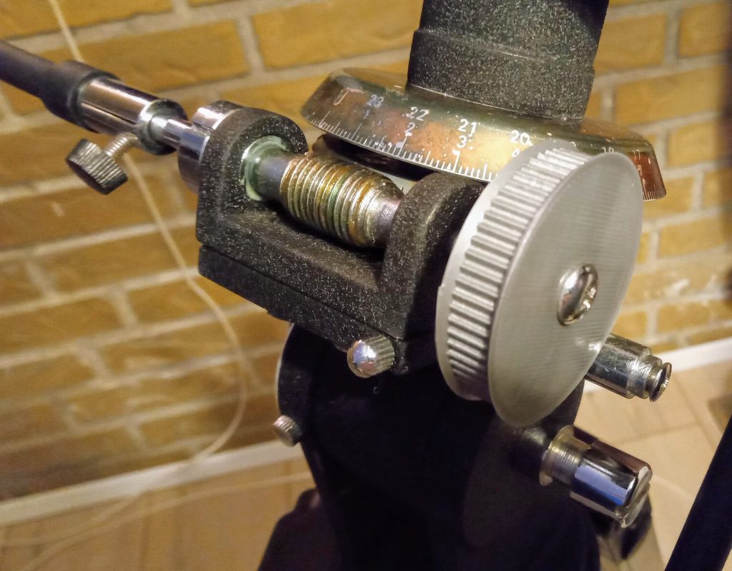
Testing and debugging had me dial the complete EqMount-gear-driver-electronics assembly/birdsnest in, attaining one revolution in 24 hours. All the way down to what the markings on the mount dial could offer. Dead on target.
I now had basic functionality; aim. But several things were missing. First of all, it was a birdsnest of wires and – well, stuff. Not pretty, and certainly not usable in the middle of a winter’s night, outside in the bitter cold in what light conditions telescopes are usually operated in; as close to zero ambient light as the operator can get. The electronics had to be tidied up on a little PCB, an enclosure had to be made, some sort of mechanical mounting, cabling & connectors to make it all practical to handle wearing gloves or mitts. Oh, and some controls. Aim is not enough, you will have to be able to aim the scope at something of your choice…
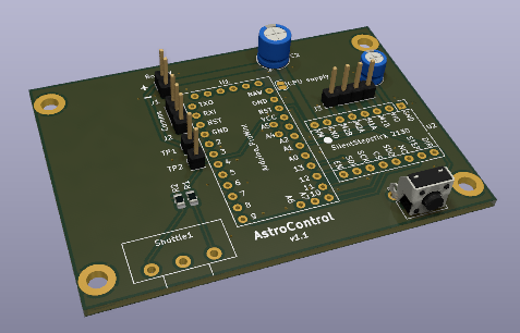
The shuttle-mechanism was made with a center-detent potentiometer and connected to the Arduino (ADC + a bit of resistor-network), allowing me to detect user input.
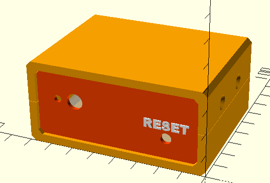
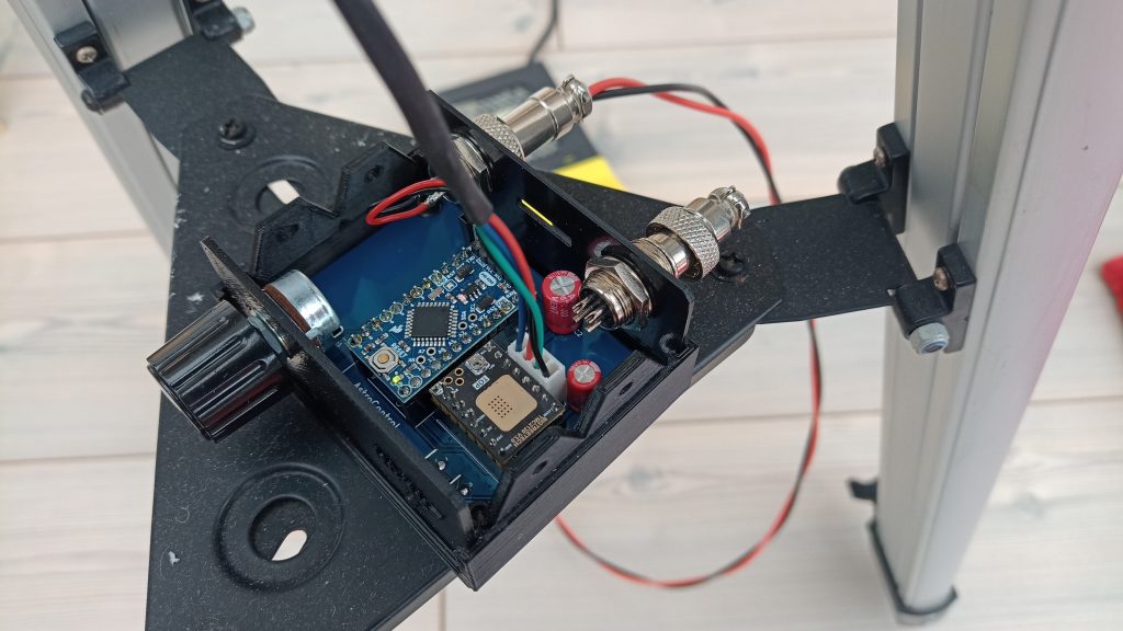
Box with potentiometer and connector cutouts + two connectors (battery and motor-cabling in non-interchangeable socket-plug sets for foolproof installation in the dark) is there, the whole entity is being test-run and tweaked.
Todo:
- Physical installation
- Battery – why not an aging car battery, suspended in the mount for stability and weight?
- There’s always something else…
Once I can close the lid, next activity is taking photos and processing them into finished images. I’ve ordered a hobbyist-grade astrophotography-camera (SVBony 205 featuring a SONY IMX179 8MPix sensor) and following install and subsequent use, software like the below-listed would be relevant:
- http://deepskystacker.free.fr/english/index.html
- https://www.astrodmx-capture.org.uk/
A vague idea related to ‘more’ in terms of control is forming. The fabled ‘Go To’ functionality, by means of connecting the controller to eg a PC, making Click2View possible. I’m not at all sure it is what I want, but being able to do it – and then doing it – seems like a whole lot of fun.
To that end, here are a few internet websites relevant to ‘goto’:
- https://sourceforge.net/projects/stellarium/
- https://www.ascom-standards.org/index.htm
- http://www.stellarjourney.com/index.php?r=site/software_onstep
Your writing feels like it’s opening a window into a world I didn’t know I needed to see.